
Nearly everyone has experienced a truly memorable power loss at home or at work, and the experience left them wanting more protection in the event of future electrical interruptions. As many are beginning to see across the variety of business and personal applications where sophisticated audio and video technologies are in use, a power loss can not only be a nuisance, but may cause permanent damage or render a whole system inoperable. Even in cases where emergency generators are in place, there will be a short-term power loss until the generator equipment can produce 100% of the power required by the load. Bridging this gap and providing increased defense against electrical calamity is a technology formerly associated mainly with largescale data centers or applications specific to IT and networks: The Uninterruptible Power Supply (UPS). Now that AV equipment is almost purely digital and rack-mountable, just like networking equipment, the same principles and best practices can also be applied to its protection.
A UPS can provide benefits in a variety of applications, and a deeper understanding of the factors important to selecting the right UPS would be of tremendous help. Let’s look at different UPS features and requirements in order to better identify the right choice for your customer or application.
Identify equipment to back up
In order to best ascertain which components in a system are essential and therefore must receive power in the event of a power outage and/or emergency, it’s a good idea to take a look at the system first as a whole and then divide it up into parts. A bit of analysis may prove that not all equipment in an AV system will require the use of a UPS, potentially saving on equipment cost and reducing the physical weight in racks and other storage locations.
From a top-level standpoint, start by asking what the purpose is for the room or building system in question. What role does it play in the end-user’s life or livelihood? How much does present and short- and long-term future success depend on the operation of this system? What value is placed on the system rebooting properly, without loss of memory from sudden power cutoff?
Next, zoom in on the individual components or parts of a facility-wide solution. When thinking about using UPS systems, a good hierarchy is to start with safety, then security, then everything else. Safety requirements are covered in detail within a commercial building’s specifications.
Large residences may also have this level of detail, but not always. Typical safety equipment might include intercom, as well as life safety systems, and these devices may or may not be located inside a rack. When considering security, devices such as electronic door locks, closed-circuit cameras and communication equipment (routers and switches) must be reviewed. The final consideration is convenience, which may pertain to AV and automation systems, unless their purpose is specified as a requirement. Remember, some things should never be backed up, such as equipment with electrical motors, HVAC.
Elsewhere in a facility, many control system components need to be backed up due to the sensitivity of those devices and the potential loss of configuration information upon reboot. (For more information on what types of AV gear should and shouldn’t be backed up by a UPS, please see the related sidebar.)
In taking this piecemeal approach to battery backup, several patterns will become apparent, allowing for more efficient determination of needs on subsequent installations.
Identify maximum load
Following the determination of which pieces of equipment will require UPS backup, it is necessary to establish the total power needs (also known as current draw, or load) represented by that equipment. Several elements of quantification go into determining power requirements, and all must be considered carefully to reduce the risk of over-engineering a system and blowing a budget instead of a power supply.
There are two basic methods for determining the required UPS rating: Nameplate calculation and the power measurement method.
For the nameplate rating calculation method, either the VA or Watt rating must be determined for each piece of equipment that will be connected to the UPS. The fastest way to discover the maximum load of individual pieces of equipment is to refer to the manufacturer’s specifications, either as documented by the equipment builder in a user manual, or by checking the back of hardware to look for a power rating sticker.
Power may be rated in Watts or Volt Amperes (VA), or some combination of those quantifiers. In order to size a UPS, ratings for VA and Watts must both be known. In cases where the VA is not listed, but the label specifies the number of volts and amps, those numbers can be multiplied together to determine VA. For example, the VA for a device specifying 120 Volts and 6 Amps can be determined by multiplying 120 by 6, for a total of 720VA. For a device with a “wide range” input rating, such as 100 – 240V, the current draw shown is typically at the lowest voltage, but as an approximation it is acceptable consider the rating to be 120V.
In order to determine Watts in cases where that rating is not specified, it’s possible to use a rule of thumb that multiplies the VA by a factor of 0.6, assuming the number of Watts is 60% of the VA for any given piece of hardware. For any equipment that is known to use Active
Understanding the power factor
A VA rating is Volts x Amps (in rms), and is referred to as Apparent Power
A Watt rating is VA x power factor, measured by a wattmeter, and is referred to as True Power
Why is there a difference in these ratings? The difference is due to something called the Power Factor, which is a ratio of the True Power to the Apparent Power.
There are electronic techniques that can bring the power factor to unity, called Active Power Factor Correction.
Power factor is a dimensionless number from 0 to 1. When the True Power and Apparent Power figures are equal, the Power Factor will be 1.0 (called Unity Power Factor). This is the optimal Power Factor. In general, unless the equipment is known to have Active Power Factor Correction, a good conservative estimate is to assume a Power Factor of 0.6.
Here are some examples of typical power factors:
Resistive loads, like incandescent light bulbs, have a Power Factor of 1.0
Reactive loads, like transformers or motors, can have a Power Factor of much less than 1, typically about 0.5 (Note: Rackmount UPS systems are not designed to provide backup power to these types of loads)
Typical electronic equipment, including modems, wireless access points, AV gear, control systems and computers, typically have Power Factors less than 1, ranging from about 0.6 to 0.9 depending on how the equipment is designed
High-end servers, routers and storage systems are typically Active Power Factor Corrected, and will have a power factor of about 1.0
Power Factor Correction, the Watts and VA numbers will be the same, and therefore the VA does not need to be multiplied by 0.6 to determine Watts. It’s not always ideal to use nameplate calculation when totaling up power requirements, because the current draw used by manufacturers to calculate VA is typically an absolute maximum value, and is unlikely to be the current draw under normal use. The power factor value of 0.6 used to find the Watt rating is also typically a worst-case value. Therefore the resulting UPS specification may be larger, and therefore heavier and more expensive than what is needed for a project.
A more precise means of determining maximum load is the power measurement method. While more complicated than simply utilizing the nameplate ratings, it can reduce instances of “over-engineered” UPS systems, and therefore be more cost effective. To use this method, a digital power quality analyzer, such as a Fluke 43B, is required in order to accurately measure all of the parameters needed. As an alternative, a true-rms digital wattmeter can be used. This equipment can be expensive, and requires an experienced operator to use and set up.
A more economical and still very specific test method is to use an in-line energy management device that is capable of measuring voltage, current, power and power factor and can be controlled by a laptop. To perform the measurement, each piece of equipment can be measured individually under actual conditions and their ratings can be summed for the maximum load, or if the equipment is powered by a vertical or horizontal power distribution unit (PDU), the total VA and Watts can be measured that way.
Once the individual power ratings for each piece of equipment requiring UPS backup are known, these can be summed to determine the total power load. Power load totals in either VA or Watts must be known to verify the size of the UPS needed for a system.
UPS hardware is rated with capacity in VA and Watts, two separate factors, neither of which can be exceeded by connected hardware. For example, a UPS may have capacity to output 1000 VA and 750 Watts. If the attached power load exceeds either the amount of VA or Watts handled by a UPS, the device will drop the load and backup will fail in the event of a transition from AC to battery backup.
It is not sufficient to satisfy the limits of just one of these ratings, either VA or Watts. Both must be separately considered. To elaborate with a hypothetical scenario, if the UPS is listed at 1000 VA and 750 Watts, failure would result in a case where total load requiring backup is 1200 VA and 750 Watts, or alternatively in a case where the total VA requirements are less than or a total of 1000 VA, but Watts are exceeded with a total 900 Watts drawing from the UPS. The total load requiring backup cannot exceed 1000 VA or 750 Watts.
Once the load is determined for each device requiring backup, and those figures are added together to determine the total load in both VA and Watts, it is possible to have a good understanding of the size of a UPS required, typically expressed in VA and Watts. Using the Total VA rating and the Total Watt rating, look for a UPS that has the same or slightly greater VA and Watt ratings to ensure that the UPS will not be overloaded – a good rule of thumb is to plan for a load no greater than 80% of the rating.
These factors can then be used in the next step of sizing a UPS—determining run time.
Define it
Dropping the load vs. load shedding
“Dropping the Load” applies to a situation when the UPS is overloaded upon transitioning to the battery and completely shuts down. All equipment connected to a UPS that “drops the load” loses power.
“Load Shedding” is a UPS capability to preserve run time by eliminating power to certain outlets based on thresholds like time (e.g., after three minutes on battery power, shut off bank number one) or battery capacity (e.g., at 30% battery capacity, shut off certain outlets/banks). Not all UPS models feature the ability (via software) to configure load shedding, but where possible, it can extend battery power for use by more critical devices. For example, a DVD player may be shut down if the power does not come back up in five minutes, in order to ensure that a router/switch remain functional. The idea is to eliminate non-critical devices from the battery backup so that other devices can remain powered during a sustained power outage.
Calculate required run time
When determining run time for a UPS, it is important to understand the environment in which the equipment is installed. First, determine the minimum requirements of the client or end-user. The type of facility and its workflow will influence the calculation of how long the equipment will need to be up during the event of a power outage when a UPS is running purely on battery, with no line voltage connected.
Next, establish whether there is a backup generator in the facility. If there is a backup generator on site, find out which locations are connected to the backup generator, and how long power will remain out until the backup generator begins to deliver power. It’s easy to overestimate how long battery backup will be necessary. Remember, the object of UPS backup is emergency or missioncritical protection. The priority is to keep equipment powered long enough for automated or manual shutdown or until generator power initiates, or provide backup for mission-critical devices such as modems and routers, and other equipment deemed essential.
Required run time is a calculation of the actual load versus the time required for the system to be on backup power. Equipment with a significant power load will draw down the UPS faster, and logically it follows that AV gear with a smaller load will draw less power. As stated in the first step of this white paper, AV equipment with large power draws, such as video displays or audio amplifiers, typically do not require backup via UPS. In most circumstances, equipment that needs to stay online draws minimal power, and therefore run time is extended.
Once load and required run time are determined, the information can then be applied to a UPS manufacturer’s calculator or determine the best match using a “Load Versus Run Time” chart.
When considering the specs of a UPS, it’s important to note there is a correlation between VA and run time. Larger VA units will typically offer longer run time for the same loads than smaller VA units. As a result, some customers go with larger units to achieve desired run time. There is a second, better option – expanded battery packs. These batteries typically measure 1U or 2U and can be daisy-chained to a UPS in order to increase the run time without additional cost of increased load capacity or capabilities. There are a few manufacturers who offer this option for select products. Not all battery backups on the market will accept extended run time batteries.
Choose a topology
Knowing the load, runtime and size of the UPS needed for a project leads to the next choice in the selection of product, which is topology. The topology of a UPS is its fundamental configuration and operation and determines how it interacts with incoming power and what happens when that power becomes unavailable. There are a number of different UPS topologies, but for this paper we’ll be discussing what are considered to be the three primary types, which are: Standby, Line Interactive and Online. Each of these different designs has its own set of benefits.
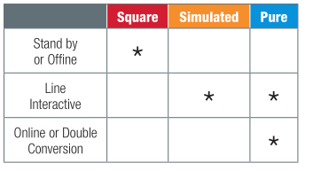
Standby/offline
A Standby, or Offline, UPS is characterized by its small size, short backup run time and lack of any voltage regulation. This type of UPS can also have a longer transfer time—the time it takes to switch to battery once AC power is not present. In general, this type of UPS generates a square wave output.
Line interactive
A Line Interactive UPS is typically rackmount, somewhat larger in size than standby models and is differentiated by the addition of Automatic Voltage Regulation (AVR). This feature allows for minor corrections, up or down, in power without switching directly to battery. This is accomplished via a buck/boost transformer and is beneficial especially in circumstances when brownouts (undervoltage events) are common. It prevents the UPS from switching over to battery, which can help with longevity of the internal battery packs.
In addition to AVR, Line Interactive UPS products generally have a faster transfer time and could be offered in two different waveform output formats. These are Simulated Sine Wave and Pure Sine Wave. We’ll explain the differences and applications of these different types of wave forms later in the paper.
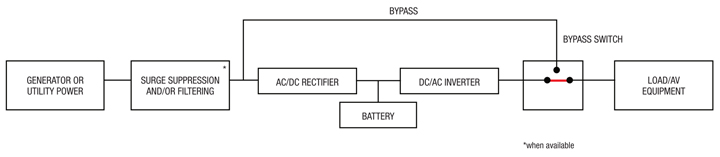
Online/double conversion
An Online, or Double Conversion, UPS is unique in that it completely isolates output power from input power. By using two inverters, input power is converted to DC and used to charge the batteries, then converted back to AC again for output to devices. Because of this configuration, the UPS has no transfer time and is always running on battery. The output is fully regulated and is always a perfect 120V, 60Hz wave, no matter what kind of input power is present. Distortion of the output waveform is very low, generally less than 3% even at full load regardless of what is happening to the utility power.
Since this is the most complex type of UPS, the size of these units can range from larger rackmount all the way to freestanding systems that can be several whole racks or more depending on the application. This is the most expensive type of UPS, however, it does provide “mission-critical” level power protection. Three caveats with the design are the increased energy consumption due to the constant charging and discharging of batteries, the decreased lifespan of batteries due to constant use and increased heat generation by the UPS.
Determine waveform type
As noted in Step Four, different topologies are associated with distinct waveforms. There are three different types of waveforms that a UPS can output depending on its design: Square Wave, Simulated (or Modified) Sine Wave or Pure Sine Wave. Each waveform type has a range of applications and advantages/disadvantages.
The three waveform types are illustrated below:
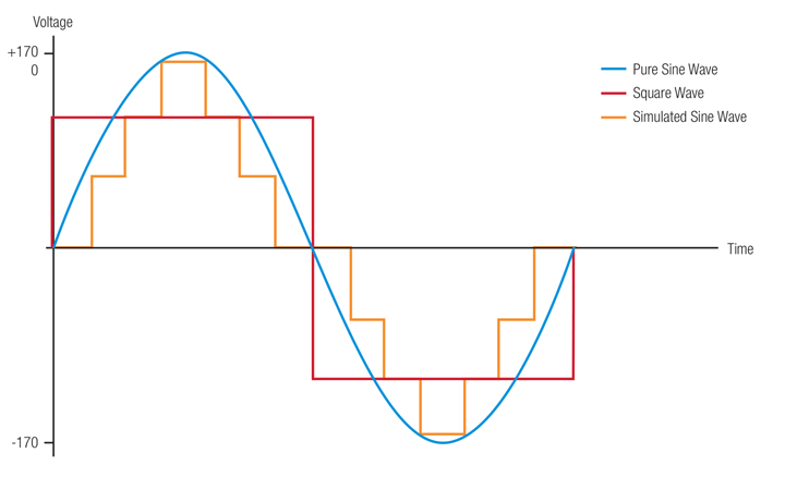
Square wave output (red trace)
A square wave UPS is potentially the most compact in size and presents the most cost effective way to provide backup power from a battery. There are several drawbacks to this topology however that make it unsuitable for AV applications. First, note that the peak of the square waveform is much lower than the sine waves. This lower peak, while still providing 120Vrms, will not fully charge up the power supply capacitors in whatever is connected to the UPS, which could result in lower headroom and less power output from audio amplifiers for example. Second, square waves contain a lot of third-order harmonics which can cause inductive devices, such as transformers, to overheat. Third, these high harmonics can wreak havoc with sensitive audio circuits. For these reasons, square wave UPS topologies are not recommended for AV applications.
Simulated sine wave (orange trace)
Modified/simulated (sometimes referred to as pulse width modulated), sine waves are similar to a stair-step and provide a better waveform than a square wave, since they more closely represent a true sinusoidal signal like that which is output from a typical wall outlet. As can be seen in the graph, the peak of the simulated sine wave is nearly equal to the peak of the pure sine wave, which allows the power supply filter capacitors in connected equipment to charge to their full voltage, thus ensuring optimal voltage performance. As load demands change, the output voltage of the UPS is regulated by increasing or decreasing the width of the peak of the simulated sine (hence pulse width modulated), so this type of UPS can maintain proper output voltage under load when it is in battery backup mode. Most power supplies within today’s electronics can accept a simulated sine wave power signal without any issue, with the exception of devices that have active power factor correction. Simulated sine wave UPS topologies also should not be used with inductive loads (motors, transformers, etc) or sensitive audio electronics due to the high harmonic content of the waveform.
Pure sine wave (blue trace)
A pure sine wave output UPS provides a waveform that is usually better than the waveform provided by utility companies, and is in fact what every power supply is designed to accept. It’s the best possible output waveform that a UPS can have and it ensures that when operating on battery, even the most sensitive type of equipment will operate without issue. The design of a UPS with this type of output is more complex and comes with a higher price point. The very low harmonic distortion of the power makes this an excellent choice for demanding audio and video systems, and it is the only type of output waveform that is compatible with power factor corrected power supplies.
So how does the choice of topologies and their associated waveforms apply to AV equipment? There are several implications. If a UPS is protecting extremely expensive and sensitive equipment, it may be advisable to use an online/double conversion topology UPS, because it will present less wear and tear on equipment and ensure that power supplies work in connected equipment power range.
Most modern power supplies are designed around IT equipment power supplies that can work on simulated sine wave just as well as on pure sine wave. However, to ensure that equipment will work well on simulated sine wave, it is important to establish whether any of the attached equipment is analog or utilizes PFC (Power Factor Corrected) power supplies. That information can be found as easily as by looking at the product description, or might be as difficult as digging deep into manuals to find the relevant details.
The most common analog equipment in AV applications are preamps and equalizers, so pay special attention to these pieces of equipment. Not only might it be important during initial commissioning, but also you may want to add analog equipment in the future. Specifying a pure sine wave UPS is an easy way to ensure the best performance. However if you are sure that you will not be using analog devices, then you will be perfectly suited with simulated sine wave, which is typically only available on line interactive and double conversion battery back ups.
Based on the fact that the square waveform offers lower quality than utility power, we do not recommend using these models for any AV applications. Constant under voltage during the “on battery” time will strain your equipment’s power supply and might lead to premature failure. Not only that, but during the operation the power supplies will generate a lot of heat.
Typical Waveforms & Topologies
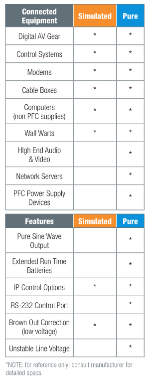
Sine wave applications
When to choose pure vs. simulated
Pure Sine Wave
- Best for audio amplifiers and analog processors, high-end video, network servers, and devices with power factor corrected power supplies
- Recommended for all electronic equipment
- Automatically corrects over-voltage and under-voltage conditions
Simulated Sine Wave
- Best for digital AV gear, computers (non-power factor corrected), control systems, modems, cable boxes
- Automatically boosts low line voltage (brown out) conditions
Additional UPS product requirements to consider
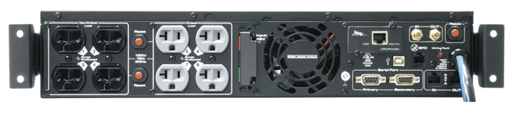
Number of Receptacles on the UPS Unit
Not all of the equipment in an AV system will require battery backup, or have need to be plugged into a UPS. It is important to determine how many devices are critical and will need receptacles that are designated as “Battery Backup”. Keep in mind that not all UPS models offer battery backup on all of the receptacles. Make sure to compare the exact specifications of the UPS to the number of critical devices in a system to select the appropriate product.
Communication Capabilities
In some instances, there will be a requirement for the equipment connected to the UPS to be monitored or controlled. Some UPS products enable this by including the ability to be networked connected or controlled by an Ethernet or a serial (RS-232 or USB) port. These types of products typically have individually switched or bank switched receptacles. They might also have such features such as incoming power monitoring and power variable thresholds. This allows an integrator to monitor the incoming power and physically set the limits where the unit will switch to battery. In some cases, this can be useful when there is equipment that might be sensitive to fluctuations in voltage level.
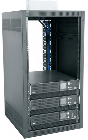
Weight
UPS models tend to be very heavy. Whenever possible the cabinets need to be rated for high loads and the UPS should be installed at the bottom of a cabinet to ensure better balance and structural integrity. This is critical when the installation is in an active seismic zone.
Automatic Voltage Regulation
AVR is the key feature that makes a UPS line interactive, and it corrects for minor fluctuations of input voltage without having to switch to battery. This is accomplished by using a special type of transformer to either lower (buck) or raise (boost) the incoming voltage once it falls outside a predetermined range, usually 120V (+/-variance dependent on manufacturer).
Appendix A
UPS run time estimation
Scenario: Home or small business wireless internet and NAS personal cloud storage protection
This system consists of three digital devices, a cable modem, a WiFi router and a Network Attached Storage (NAS) device with 16 Terabytes of storage. A site survey has determined that the utility power can be unstable with frequent brown-outs, voltage surges and occasional service interruptions. To protect sensitive data stored on the NAS, it was determined that a line-interactive UPS offered the best protection and would allow the user to set up the NAS to gracefully shut down in the event of a total loss of utility power. A second requirement was to maintain connection to the internet for up to 30 minutes.
Looking at the equipment nameplate ratings the following was noted:
- Cable modem/router, 115-240VAC 0.5A max
- WiFi router, 100-240VAC 0.8A max
- NAS device, 19VDC up to 6.32A
So we have a mix of data with AC current ratings and DC voltage and current, however as we learned previously, to specify a UPS we need to know the load demand in Watts and VA. Some basic math is required. Both the cable modem and WiFi router are powered by external power supplies, or wall warts. We will use a line voltage of 120VAC and multiply that number by the max current draw given for each. Remember that we are just multiplying volts and amperes, so the result will be VA.
- Cable modem VA rating = 120V x 0.5A = 60VA
- WiFi router VA rating = 120V x 0.8A = 96VA
The data sheet for the NAS device only tells us the DC power requirements, so an additional calculation is required. The power supply for this NAS is similar to a typical laptop power “brick”, and those types of power supplies can have efficiencies up to 90%, meaning that only 10% of the power that is consumed from the AC line is wasted as heat. With that in mind we first calculate the DC power to be 19VDC x 6.32A which equals 120 Watts (when calculating power for DC current and voltage, the result is always in watts, not VA). Now we know the load power, but to find the AC power requirement we need to account for efficiency so AC power = DCpower/0.9 = 120W/0.9 = 133Watts AC power.
Since our load was calculated in watts, our AC power remains in Watts. We are left with two numbers in VA, and one in Watts but remembering that we must select a UPS based on both VA and Watts some conversions are required. The relationship between Watts and VA is dependent upon the Power Factor that each device presents to the AC line, and a good rule of thumb is to use a Power Factor of 0.6.
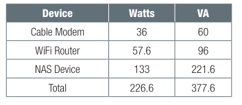
Since Power Factor is the ratio of Watts to VA (actual power to apparent power) we can find whatever quantity we don’t know as follows:
These are the estimated load demands in both Watts and VA. For this example we are going to select a Line Interactive UPS that has automatic voltage regulation (AVR buck and boost, to account for over-voltage and under-voltage, respectively) and a pure sine wave output voltage when in battery mode.
The UPS manufacturer publishes the following run time chart for a UPS rated at 1000VA/750W (on left side).
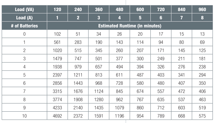
From the chart we can see that with a load VA of 360 our run time would be 34 minutes, which is very close to our requirement for a 30 minute run time. This UPS would provide excellent protection for the NAS device and allow the system to ride out any line voltage disturbances for up to 30 minutes.
References
1. Pacific Gas and Electric Company. Uninterruptible Power Supply http://www.pge.com/includes/docs/pdfs/mybusiness/customerservice/energystatus/powerquality/ups.pdf
2. Microchip. AN1279 Offline UPS Reference Design Using the dsPIC DSC http://ww1.microchip.com/downloads/en/AppNotes/01279A.pdf
3. EETimes. Standby and uninterruptible power supply tutorial. http://www.eetimes.com/document.asp?doc_id=1273195
4. ON Semiconductor. Power Factor Correction (PFC) Handbook. http://www.onsemi.com/pub_link/Collateral/HBD853-D.PDF
5. Freescale. Single Phase On-Line UPS Using MC9S12E128 Designer Reference Manual. http://cache.freescale.com/files/microcontrollers/doc/ref_manual/DRM064.pdf?fasp=1&WT_TYPE=Reference %20Manuals&WT VENDOR=FREESCALE&WT_FILE_FORMAT=pdf&WT_ASSET=Documentation&fileExt=.pdf
6. IEEE Std 1100-1999. IEEE Recommended Practice for Power and Grounding Electronic Equipment. Chapter 7
v.good information , thanks a lot .